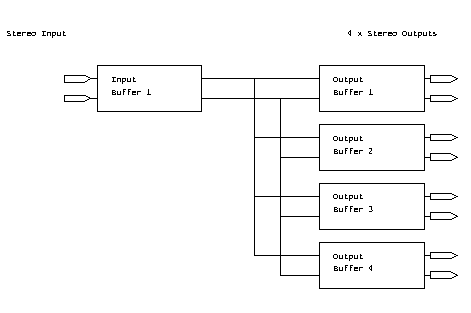
Chris Baron wrote to me "Paul, I need a 4-way buffer amp, to replace a nastly looking chocolate block, that distributes our signal". So in response, and 100% based on the circuit used in Article #2, here is a simple 1-in 4 out buffer amp (=signal distribution amplifier). If 4 channels isn't enough, then just keep adding output buffers until you have enough!
The circuit shown is for one channel: double this for a stereo buffer! If you want to have stereo in, and mono out, look at article 2 to see how to combine the L and R inputs.

The input signal comes in on the left, and is buffered. This then feeds 4 output buffer amplifiers.
The circuits below show just one channel, so build it twice, once for the Left channel, once for the Right channel
Hi-res large Circuit in GIF format (22k)
Starting at the left of the circuit, the input signal is capacitively coupled (to eliminate DC offset problems on the inputs), and buffered. It is possible to change the gain on the input buffer by adjusting the feedback resistor value, or even replacing it with a preset pot. The capcitor (c2) is optional, and is typically something like 1nF (1000pF), and is there to stop nasty high-frequency noise being a problem.
The gain of the buffer is Rf/Rin (Rf is the feedback resistor, R2, and Rin is the input resistor, R1). Currently, the circuit has a gain of 1.
After the input buffer, the signal then feeds 4 output buffer amplifiers... if you need fewer or more outputs, just remove / add the output buffers as needed! The outputs are NOT capacitively coupled - if you use the specified op-amps, any DC offsets will be so small that they can be ignored. Besides, most equipment you connect the buffer unit to will have their own input capacitors.
Each buffer inverts the audio signal phase: because all audio paths have TWO buffers, the phase of all outputs is the same. "Why is this important?" you may ask: well, by keeping the phase the same, it means that if you feed the signals via a desk, and then switch between the desk output and the "station output" of this buffer circuit, there should be no clicks (assuming that your mixer doesn't invert the phase!!)
Not shown on the circuit are decoupling capacitors. These should be 100nF, and should be fitted one to each power rail, adjacent to each IC. So if you have 3 IC's, you'll need 6 x 100nF capacitors!
The way I've designed it, the circuit uses a dual op-amp for the input, and a pair of quad op-amps for the outputs.... you don't HAVE to do it like that... do whatever is convenient!
Do NOT use a switch-mode supply! SMPSU's often create audio noise... that's the last thing we want on this circuit! At the powers we are talking about, a linear PSU is not a big deal.
The circuit will work just as well with any supply from +/-12 volts to +/- 18 volts: the higher the supply, the more audio headroom you will have. However, make sure your op-amp IC's can take the voltage: some versions of the TL071/2/4 range only go to 15 volts)
It may be that you have a suitable PSU in another bit of equipment: if so, then you can possibly use that. The 50 to 100ma quoted above is a very conservative estimate.
If you feel up to building youir own PSU, then take a look at Article #3, which describes how to build a simple linear PSU.
If you choose to build more or fewer channels, just select a suitable device. If you end up with one or more op-amps unused, then simply connect the -ve signal input to the output, and the +ve signal input to 0v (this makes what is called a "follower" circuit).... that will stop the op-amp going noisy, latching up, or consuming excess power.
The TL06x range of op-amps are low-power versions (with a matching lower performance) of the TL07x, whilst the TL08x range are a lower cost version, with a worse noise figure. Wilst they may seem to be ok, I'm not going to vouch for how they cope with longer cable runs (that comment applies especially to the TL06x range) that are often needed in radio studios.
Many other modern op-amps are also suitable: however, it is generally NOT worth paying huge amounts for "state of the art" high-spec devices: at the end of the day, your station output is feeding either (a) a BT landline, then a 100 v line amplifier and finally piezo earpieces at the patient end; or (b) a MW transmitter which is listened to on a low-grade radio ("Walkmans" may have a good FM performance, but their MW performance is usually very close to crap!). In all cases, the audio quality of the TL07x range of op-amps far exceeds the quality of all the other downstream equipment!!!! (I have won that arguament MANY times!!!)
(plb, rev 1, Oct 2000)