This is actually VERY easy to do, and all you need is an isolating transformer at each end, and some cheap op-amps to drive / receive the signal, along with a few resistors etc.
Often, you need to send a signal in each direction... for example, you want to send a signal from the wards to the studio, and you'd also like to hear from the studios up in the ward. All you do there is to run 2 pairs of wire, and have a transmit and receive circuit at each end.
If you want to be clever, it is also possible to run a THIRD signal using 2 pairs.... I'll describe that later!
This article isn't really intended as a standalone "project", but is really more of a tiny "Building Block", which you may wish to include in something else (eg an Ward O/B unit).
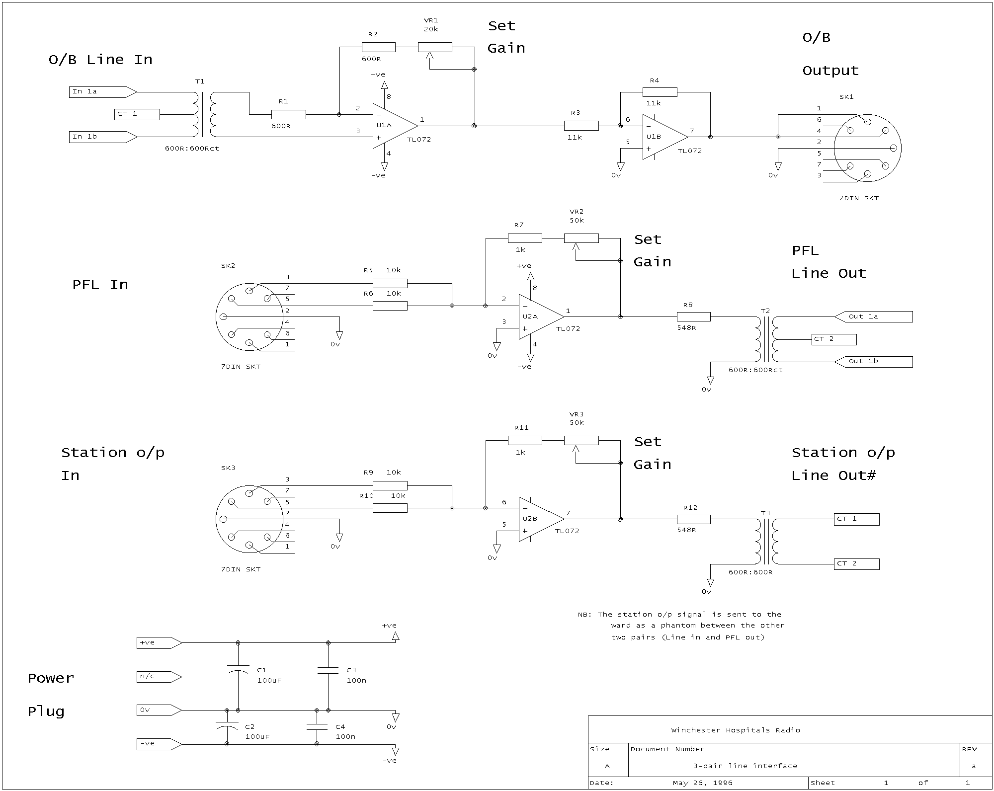
The other half of the equation is how to correctly RECEIVE that signal.... again, it is simple: feed it through a 600-600 ohm line transformer, put a 560 to 600 ohm resistor across the secondary, connect one end to 0v, the other to a high-impedance buffer amplifier (eg 10k input).
The transformer's job is simple: it isolates the line from each end, and eliminates any earth-loops. In addition, it gives you a balanced output.
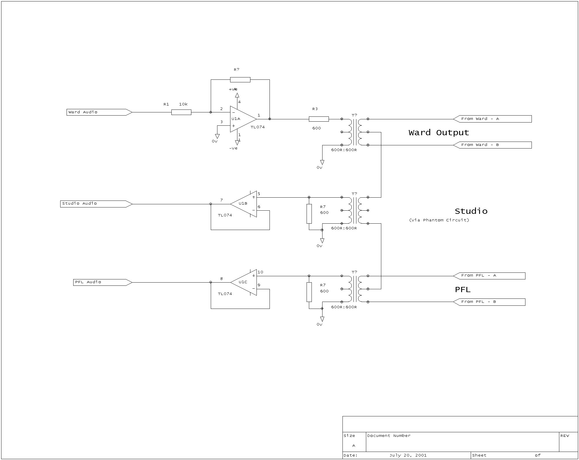
To get 3 signals down 2 wire we have to get clever: we use what is called a "phantom circuit". This is created by using a transformer with a centre-tap on the line side, and connecting the third signal between the two centre-taps.
How does this work? Well, when we drive a signal via a centre-tap, it goes down both wires of the pair identically (in what we call "common mode") and so doesn't affect the existing signal (which is a "differential" signal across the 2 wires of the pair). So, now just pretend that each "pair" is actually just a single wire.... hey, we have another "pair", where each "wire" is actually one pair of wires!
To recover the signal, we do the same again: we use centre tapped transformers, and recover the differential signal from the centre-taps.
Because the pahntom pair is on the line-side, we actually connect a third transformer between the centre-taps.
If you take a look at the first drawing, you should easily see how the phantom connects... of course, if you don't need that 3rd signal, just ignore that bit, and use 2 normal transformers!
Lets take a look at the diagrams. The first pair show the Ward end circuit, the second pair are the Stusio end:
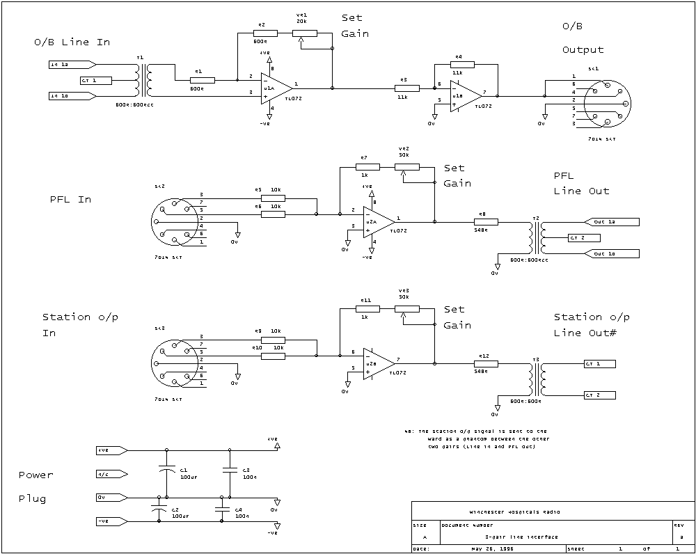
Smaller Studio Circuit in GIF format
2) Stereo inputs: If you take 2 signals (ie L and R) and mix them, then the resulting signal is twice as big.... so if you use a stereo input, and drive down a mono line, then you already have your gain of 2!
To give an op-amp a gain of 1, use the same value for input and feedback... we tend to use 10k. To get a gain of 2, use a 20k on the feedback instead of the 10k!
On the Ward circuit, you will see an op-amp without any resistors: this is a unity-gain follower circuit. The disadvantage of this is that you can not vary the gain at all!
Ok, that's enough to get you going.... just shout if you need any more info!!!
(plb, rev 1, July 2001)