Historically, we used a similar device, using XLR connectors for the mic inputs: this required that we used a MUCH larger aluminium box... by instead using 3.5mm jack sockets, we could make the new box a LOT smaller, making it a lot easier to wear. In fact, it is so small that you could easily just velcro it to the radio mic transmitter belt-pack.
Before going into details, here's a couple of important notes:
- Many PC mics require approx 5 volts (at low current) to operate: this is applied to the "ring" of the 3.5mm connector
- The Trantec radio mic transmitter that we use puts out 9v (very limited current): this has to power 2 mics and the mixer circuit!
The fact that the radio mic is battery powered means we don't have to worry about mains hum, but it also means that there is very little power available to us.
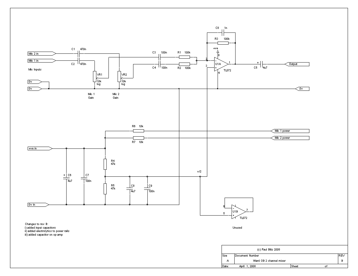
The core of the circuit it actually very simple: it is a unity-gain inverting 2 channel mixer, preceded by 2 gain controls. Cheap condenser mics seem to have an output impedance of about 1k, so we use 10k pots to not load this. Similarly, the amplifier has a 100k impedance, so as not to load the pots! The inputs are capacitor coupled, as it seems that many PC mics have DC on the audio.
Because the circuit has to run from a single voltage rail, we have to generate a "midpoint", "v/2". This is done with the two 47k resistors. This feeds the "+" input of the op-amp. Also, all audio inputs and outputs must be capacitively coupled, thus the input capacitors (anything over 100nF will do), and the output capacitor (anything over 4.7uF is fine... note that the positive goes towards the op-amp).
The only reason I used a TL072 op-amp is that I have a stock of them...which meant I had an unused op-amp. If buying a device, then you might wish to use a TL071 (single op-amp), but note the different pinout! Other modern op-amps could also be used (I would have used a CA3140, if I had one...) Don't use a "741" op-amp, they are old, crap, and use far to much current! The 1n capacitor in the feedback chain of the op-amp is to provide some HF rolloff, and thus stability.
The power for the 2 microphones comes via 10k resistors fed from the input voltage.
Looking at the physical side of things: I fitted the two 3.5mm (stereo) jsck sockets to the end of the box
(which becomes the bottom when clipped to belt / velcro'd to radio tx). The "Sleeve" is 0v, the "ring"
is power, and the "tip" is audio.
I used two 10k miniature log pots (and knobs) for the volume (maplins part # JM77J, 69p). The box was one I happened to have, as was the belt-clip! You might want to use velcro.
(Of course, you COULD use a local battery to drive the circuit, rather than take power from the radio-mic TX,
but that means yet ANOTHER battery to have / change / charge!)