By now, you know that you need a regulated PSU, but only have an UNregulated one available.... in Article 3, I wrote:
Using an UNregulated PSU
Ok, what about the idea of using a pre-built & cased UNregulated PSU. Again, you need to put on a mains plug, and connect the output wire to your box with a suitable connector.Inside your equipment, you need to take the input, and regulate it. This is actually simpler than you might think: Maplin sells "regulator cards" (see the "Projects" section of the catalogue), both pre-built and DIY that you can use. They can be made to supply almost any voltage needed.
Alternatively, you can build the same regulator circut onto a bit of "Veroboard".... if you are also building something else, then this may be convenient.
In either case, do not try to leave out any of the capacitors: the smaller ones (ie < 1 microfarad) are essential to stop the regulator IC from bursting into oscillation. If you build it yourself, then fit these as close as you can (and in any case within an inch) of the regulator IC.
This article tries to explain what a regulation circuit is, and how you build one.

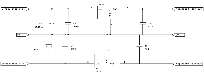
Bigger version of the circuit in GIF format
An unregulated PSU puts out DC at a somewhat variable voltage (depending on what load you apply!) with a lot of mains hum on it. The regulator does 2 things: first it makes the voltage stable, and second it drastically reduces the mains hum on the outputs.
There are many ways to build a regulation circuit, but our life is greatly simplified by a range of ICs that do 95% of the job for us. This is the 78xx and 79xx range of Voltage Regulators. The 78xx family are POSITIVE voltage regulators, and the 79xx family are NEGATIVE voltage regulators.
They are available in several voltages... the number after the 78 or 79 indicates the voltage... so a 7805 is a +5 volt device, a 7915 is a -15 volt device.... simple, isn't it?
To make these devices work, you need to feed them with a voltage that is about 3 to 6 volts higher than the regulated voltage you need. Watch out, many unregulated supplies outputs drop noticibly under load: you need that 3 volts difference UNDER LOAD! So, for a 12 volt regulated supply, you should be looking for 15 volts on the input. If you measure an unregulated supply, you may find that an unregulated unit claiming to give out 12 volts may give out 15 volts: just try it & see if it's ok!
Ok, lets's look at the circuit in detail:
C1/2 are reservoir capacitors. The theory says that this should be approx 2000uF per amp.... for most of what you are going to want, I would bet that your need is for well under HALF an amp.... so a 1000uF capacitor will do fine. It's voltage rating should exceed the input voltage by about 25% (to take into account the fact that the input voltage can rise under no-load conditions)... for a 12 or 15 volt regulator, use a 25 volt capacitor... for a sub-10 volt regulator, a 16 volt capacitor will be fine.
If your unregulated supply has a suitable capacitor, you can reduce the size of C1/2 further. However, do NOT leave it out.... put in, say, a 100uF capacitor.
C3 to C6 are (non-polarised) decoupling capacitors, and should be good-quality 470nf (0.47uF) high-frequency decoupling capacitors: they are there to stop the regulator IC from oscillating at a high frequency. Do NOT omit these, nor go for a smaller value.
The regulators themselves are available in 2 versions: the "TO220" devices are rated at 1 amp (and will need a heatsink for that too!!), whilst the "TO92" devices (look like tiny transistors) can manage 100mA. For simple op-amp circuits, the 100mA devices will probably be more than adequate! None of them are particularly expensive (eg under £1 each).
If you need just a single voltage, just use a single regulator. The circuit I have done is for a dual (ie +ve / -ve) supply, and uses two regulators etc.
How do you build the circuit? Vero stripboard is fine for it, as long as you apply a couple of simple rules: (1) the decoupling capacitors (ie c3 to c6) should be as close to the regulator IC as possible.... anything more than 1 cm is probably too far! (2) Any wires used as links on the board should be at least the same size as the wire on resistors or capacitors... do not use thin wire.
Note that this circuit requires a DC input.... DO NOT apply AC to the input (ie DO NOT connect a transformer directly to the input!): if you do, you are 99.99% likely to blow the whole thing up!
(plb, rev 1, Mar 2001)