The simplest thing is to connect a switch across the play button... oh, and you'll need to also have one on the pause too.... nice idea, but most desks have a simple "close to start, open to stop" switch... and that wont work, will it?
What you need to do is to convert the "switch closure" to a momentary switch-closure for the "play" button... and the "switch opening" to a momentary switch-closure for the "pause" button.
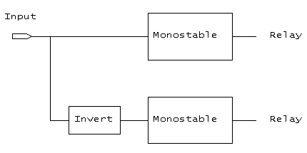
The circuit described here takes a simple switch-start as input, and pulses two reed-relays. It is designed to be fitted INSIDE your equipment, and is powered from the unit's own power supply. The circuit includes its own simple on-board 5 volt regulator, so it will work from any voltage between about 7 and 20 volts DC.

We also invert the signal, so that we also get a pulse when the input has a negative transition.
The end result is that when we switch the input to 0 volts, one relay will pulse, and when we re-open the switch, then the other one pulses.
Not shown on the block diagram is a voltage regulator. This takes in a rather indeterminate voltage (which we find somewhere inside the CD / Cassette player) and makes it into a stable 5 volts, which the circuit needs.
The circuit takes very little current.... the relays typically use 10mA when operating, and the rest takes less than 10 mA.
High-res Circuit in GIF format (30k)
The output is a 5 volt operated reed relay: don't use any other sort of relay, as it won't be reliable, nor will it last as long (and it may audibly "clunk"!). The relay contacts are simply wired across the play and pause buttons. We use those nice 14-pin DIL reed relays: the Maplin DC91Y costs only £2.72 and includes the back-emf relay inside it (make sure you connect the coil the right way around, or it won't work!).
The relays are each driven by a 2N7000 fetlington (Q2 and Q3): these lovely devices take a TTL (or CMOS) input - no resistors needed - and can drive relays, lamps etc. Lovely devices, and cost only 22p at Maplins (part # UF89W).
DO NOT USE ANYTHING ELSE! The circuit won't work with anything else!
The 2N7000's are pulsed by the two monostable multivibrators: the 74HC221 (U2) conveniently contains 2 of them for us! The pulse width is set by the resistor (R4 / R5) and capacitor (C5 / C6). As specified, the pulse width should be about right. Increase the capacitor to make the pulse longer, decrease it to shorten the pulse.
The 74HC221 multivibrator is triggered when the input goes from low (0v) to high (approx 5 volts). Thus if we directly drive a monostable from a "switch to ground", the monostable will trigger when the switch OPENS... ie it works as a STOP pulse. To make a monostable work as a START pulse, we need to turn it upside down - the techie term is INVERT it.
The top multivibrator (U2a) is driven directly by the input, and thus drives the STOP relay. The lower one (U2b) is driven by an inverted input, and drives the START relay... the inversion is done by Q1.
The input should be an isolated switch closure (just like on most mixers!), connected between the input and 0v.
You should, as a matter of course, fit a 10n or 100n capacitor across the power pins of the IC, as close to the IC as sensible.
The whole circit runs from a simple +5 volt supply: this is derived from a suitable voltage inside the equipment (see note). Q1 is a 78L05: this is a 100mA +5v regulator (Maplins part #QL26D or AV02C, cost under 50p). These devices can be run from an input voltage between +7 and +30 volts... however, if the input is much over 15 volts, it may get excessively hot.
(note: inside your CD etc, look for a big capacitor, near where the power goes to the main board from the transformer, and measure the voltage to see if it's suitable... it probably already feeds a regulator for it's own power supply... usually you'll find this fairly quickly)
(plb, rev 1, Nov 1999)