Article Index Home
Article #8: Simple Output Circuits
copyright ©2000 Paul Blitz
Introduction
Often, when you have built a simple (or not so simple...) circuit, you want
it's outputs to actually do something! Originally designed for use with the
Silence Detector (see Article 1), they
can be used with almost any other circuit.
Article 7 describes one simple
circuit, to remote start / stop Cassette Decks / CDs etc. Here are a few
more, simpler, circuits.
All of these circuits are designed to be driven by logig levels: both TTL
levels (0.8v for low and 2.4v for high) and CMOS levels (0v for low and 5v
for high) will work fine.
LED Driver

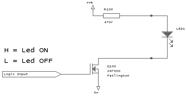
The circuit operation is simple: if the input voltage is high, it turns on
the fetlington, which allows current to flow in the LED, which lights. If
the input voltage is low, then the fetlington remains off, so no current
flows through the led, and it does not light.
The "+ve" voltage supply can be anything from +5 volts to say +20
volts. Most LEDs need a drive current of about 5mA to operate. For +5
volts, R100 needs to be 470 ohms, as above. For +12 volts, increase it to
2k2 ohms. For +20 volts use a 3k3 ohm resistor.
These values are very approximate: it is quite safe to double the resistor
value (gives about 2.5 mA) or to half the resistor value (gives about
10mA), or to double it.
For up to (and including) a 12 volt supply, a 1/4 watt resistor is
sufficient, but for higher voltages you may need a 1/2 watt one.
Note that LED are polarity sensitive: as long as you have a series
resistor, it's quite ok to put it in-circuit either way, to see which way
around the pins need to be.
NEVER use an LED without a series resistor: if you do, it will glow
brightly for a few seconds (if the right way around) and then fail!
The circuit as shown is specifically designed to use a 2N7000 fetlington:
do NOT use any other device (unless you re-design the circuit!). They are
available from Maplins, part number UF89W, and cost less than 40p
each, and about 25p each if you buy 25 of them!
Open Collector output

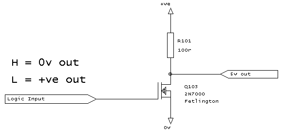
Hey, have you noticed that this circuit looks very much like the one above!
If the input is high, then the fetlington will turn on, and the output will
be grounded. If the input is high, then the output will be "floating".
Again, note that this circuit is specifically designed to use a 2N7000
fetlington.
Relay Output

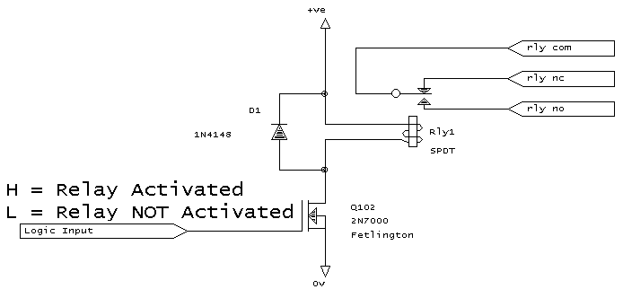
Again, we use a fetlington, but rather than driving an LED we are driving a
relay.
Note that there is a diode fitted across the relay coil: this is a "back
emf diode" and it is important that it is fitted. Without it, the circuit
may appear to work fine, but it is quite likely that after a short while
the fetlington will stop working... not what you want! You can use almost
any sort of diode: a small 1N914 / 1N4148 is fine, but you could just as
easily use something like a 1N4001.
Obviously you need to match the relay with the supply voltage used. Be
aware that some relays can take quite a bit of current.
Reed relays are a good choice for 2 reasons: first of all, because they are
sealed, the contacts don't wear out like normal relays, and second, they
tend to use less current to operate. Besides, they are neat and small!
Maplin do some very nice, low cost, on-off (ie NOT changeover) reed relays
that work on 5 volts, and take only 10 mA. The parts numbers are
JH12N for single pole (costs under œ2) and JH15R for double
pole (about œ2 each).

This circuit is similar to the open collector one above, except that it has
a pull-up resistor on it as well.
As a result, if the input is high, then the fetlington is turned on, and
you get a 0v output. If the input is low, then the fetlington it turned
off, and the resistor pulls the output to the +ve voltage.
Unfortunately, the current output available is limited by the resistor (for
a 5 v supply, with a 100 ohm resistor, the limiting current is only 50 mA.
If you need to feed more current than this, then it's probably better to
use a relay (see above). In that case, connect one contact of the relay
pole to the supply voltage via a fuse to protect your circuit
against an external short-circuit.
And Finally....
If you need something slightly different from the above, then let me know,
and I'll add a suitable design to this article.
Finally, if you need any help with these circuits in any way, then feel
free to email me with your questions.
(plb, rev 1, Jan 2000)
Article Index
Home


